Welcome to Guangzhou Tongsen Electronic Technology Co., LTD. Website!


PCBA Test Overview
Functional testing (FCT) also uses a nail bed fixture; however, it verifies that the DUT operates as expected, rather than testing the electrical connections between individual networks. For example, it confirms that the firmware is functioning correctly. This information is critical for verifying that the hardware is functioning correctly!
Printed Circuit Board Assembly (PCBA) processes involve various types of testing, such as AOI, AOX, ICT, smoke testing, black box testing, and regression testing. Functional testing (FCT) powers the device and verifies expected operation.
Printed Circuit Board Assembly Testing Stages
The Printed Circuit Board Assembly (PCBA) process typically includes the following steps.
After components are soldered to the PCB, a series of inspection and testing processes are performed on the printed circuit board assembly. The board is commonly referred to as the Device Under Test or DUT. We will briefly outline each step below.
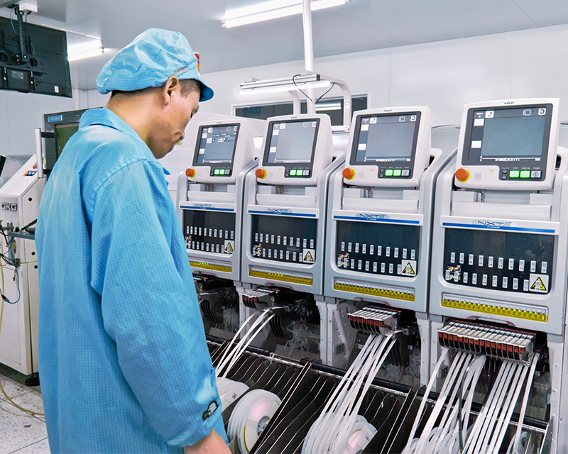
Automated Optical Inspection
Automated Optical Inspection stations use cameras to take images of the board, then use computer vision to verify that all components are installed and the solder joints are good.
Images are taken using various light sources and may also use cameras from multiple angles. AOI identifies issues such as missing components or tombstoned resistors.
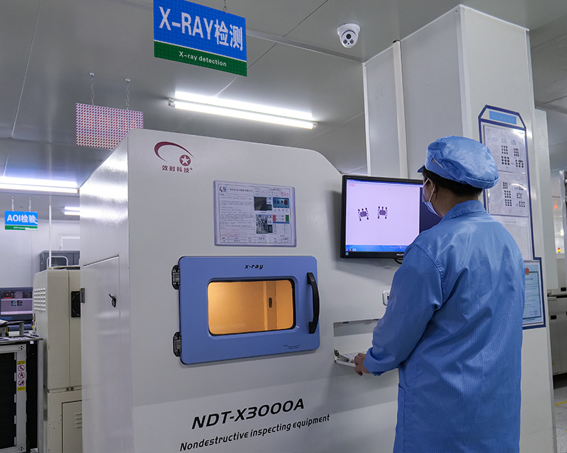
Automated X-ray Inspection
Automated X-ray Inspection (AOX) is similar to AOI. However, instead of processing optical images, it uses computer vision to process X-ray images. This test verifies all solder connections on the board, including those hidden underneath components, by analyzing the X-ray images. AOX test stations are well-suited to verify that Ball Grid Array (BGA) components are properly connected to each PCB product.
Flying Probe and In-Circuit Test
Flying probe and In-Circuit Test (ICT) both use the same methodology to test the DUT. These test methods use spring-loaded probes to measure resistance, capacitance, and other key characteristics between test points on the product.
It is best to have a test point for every net on the DUT. Each spring-loaded probe in the test fixture has a test point so that the flying probe and in-circuit test stations can verify that there are no shorts or opens and confirm that each component is correctly placed on the DUT.
A flying probe tester uses robotic test probes to quickly contact each test point and take measurements between that test point and every other test point. This process can take up to 30 seconds.
Flying probe stations do not require custom fixtures, making them ideal for getting test results from low-volume production runs.
In-circuit testers (ICT fixtures) are better suited for high-volume production. The test system contains many test probes or spring-loaded probes to contact each test point on the DUT. They are also known as bed-of-nails testers.
The bed-of-nails mechanical fixture in an ICT test system must be custom designed for each DUT. This adds cost and development time, typically meaning they are only cost-effective for high-volume PCBA production. These fixtures can achieve the same test results as flying probe systems but in a fraction of the time.
Another key difference is that flying probe and ICT testing do not apply power to the device under test.
Functional Test
Functional Test (FCT) also uses a bed-of-nails fixture; however, it verifies that the DUT operates as expected, rather than testing the electrical connections between individual nets. For example, it confirms that the firmware is operating correctly. This information is critical to verifying that the hardware is working correctly!
Typical tests performed during functional testing include:
Verifying that the voltage rails produce the correct voltage when the DUT is powered on;
Programming microcontrollers and memory;
Verifying various communication buses on the device.
RECOMMENDED NEWS

High-end Custom Services: SMT Chip Processing Meets Diverse Industry Needs


(Telephone contact)
Email:
Address: Room 502, Building 1, No. 13, Bohua 4th Road, Huangpu District, Guangzhou City
COPYRIGHT © 2025 Guangzhou Tongsen Electronic Technology Co., Ltd. All rights reserved.