Welcome to Guangzhou Tongsen Electronic Technology Co., LTD. Website!


State-of-the-art SMT production line process in PCB manufacturing
Surface Mount Technology (SMT) is an aspect of electronics assembly where electronic components (also known as surface mount devices or SMDs) are mounted directly onto the surface of a printed circuit board (PCB). SMT is favored in the industry for its cost and quality efficiency. In the SMT production line process, components are directly soldered onto the PCB surface, and the precise positioning and mounting of components are accomplished through equipment such as pick-and-place machines.
Surface Mount Technology (SMT) is an aspect of electronics assembly where electronic components (also known as surface mount devices (SMD)) are mounted directly onto the surface of a printed circuit board (PCB). SMT is favored in the industry for its cost and quality efficiency. In SMT production line processes, components are directly soldered onto the PCB surface, with precise placement and mounting of components achieved through equipment such as pick-and-place machines.
What is Surface Mount Technology (SMT)?
Surface Mount Technology (SMT) is an advanced assembly and manufacturing method that allows for the direct mounting of electronic components onto a printed circuit board (PCB). This advanced process streamlines automated production, efficiently completing the assembly required for functional boards. Any electronic component mounted in this manner is referred to as a surface mount device (SMD). Compared to traditional assembly, SMT bypasses the step of inserting components through holes; instead, components are directly soldered to the board via reflow soldering.
SMT Manufacturing Process
The SMT manufacturing process involves three key stages: solder paste printing, component placement, and reflow soldering. This structured approach ensures precision and efficiency in directly assembling electronic components onto the printed circuit board.
Solder Paste Printing
In this stage, a printing machine uses a pre-made stencil and squeegee to apply solder paste onto the printed circuit board (PCB). The solder paste, composed of flux and tin, aids in the connection between the surface mount components (SMCs) and the pads on the PCB.
In this process, achieving precise coverage of solder paste on each pad is crucial. Inaccuracies in the solder paste can hinder the establishment of connections when the solder melts in the subsequent reflow oven stage.
Maintaining quality control in solder paste printing is essential. Any defects detected at this stage can trigger more serious downstream issues. Stencil design is critical, requiring the assembly team to ensure a repeatable and stable process. While many solder paste printers have automated inspection capabilities, some utilize external machines with 3D technology for a more thorough assessment. These external inspection devices evaluate factors such as the amount of solder paste on each pad, providing a comprehensive analysis rather than a simple assessment of the printed area.
Component Placement
After inspection, the PCB proceeds to the component placement stage in the SMT assembly process.
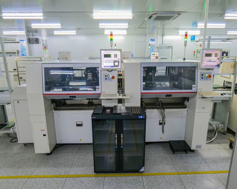
Each component to be placed on the PCB is picked from its packaging using vacuum or collet nozzles. A pick-and-place machine then precisely positions individual electronic components onto the solder paste previously applied to the printed circuit board (PCB). These machines are not only highly precise but also incredibly fast. Top-tier machines can place up to 80,000 individual components per hour, showcasing the efficiency of this advanced assembly process.
This process must be precise, as any incorrectly placed solder can lead to costly and time-consuming rework.
Reflow Soldering
Reflow soldering is a crucial stage in the assembly after surface mount components (SMCs) are placed on the printed circuit board. The PCB is conveyed into a reflow soldering oven, undergoing a carefully designed soldering process in different temperature-controlled zones:
Preheat Zone: The initial zone gradually raises the temperature of the entire PCB and its attached components simultaneously. The temperature rises at a controlled rate (1.0℃-2.0℃ per second) until a range of 140℃-160℃ is reached.
Soak Zone: In this stage, the board is held at a stable temperature between 140℃ and 160℃ for a duration of 60-90 seconds.
Reflow Zone: The PCB then enters a zone where the temperature gradually increases (1.0℃-2.0℃ per second) to a higher range of 210℃-230℃. The high temperature melts the tin in the solder paste, effectively soldering the component leads to the pads on the PCB. During this process, the components remain in place due to the surface tension of the molten solder.
Cooling Zone: The final section ensures the solder solidifies as it leaves the heated area, preventing joint defects.
After reflow soldering, a final inspection is performed using a 3D Automated Optical Inspection machine (AOI). This ensures the expected solder joint quality and identifies any errors in the SMT process. Using machines at this stage improves efficiency and accuracy compared to manual inspection.
For double-sided PCBs, these soldering processes may be repeated. This involves securing the SMCs in place using solder paste or adhesive. This meticulous reflow soldering approach ensures the integrity and functionality of the soldered connections in the electronic assembly.
Main Equipment of SMT Production Line
A Surface Mount Technology (SMT) production line involves several key pieces of equipment that work together to assemble electronic components onto printed circuit boards. The main equipment in an SMT production line includes:
Stencil Printer: The stencil printer applies solder paste to the PCB using a stencil, ensuring the solder paste is precisely placed in designated areas.
Pick-and-Place Machine: This automated machine picks up electronic components and accurately places them onto the PCB according to design specifications. It can handle various types and sizes of components.
Reflow Oven: The reflow oven is where the PCB, its components, and the solder paste undergo a controlled heating and cooling process. This melts the solder, resulting in strong electrical connections.
Solder Paste Inspection (SPI) Machine: The SPI machine inspects and verifies the accurate deposition of solder paste on the PCB before component placement, ensuring the quality of the soldering process.
Automated Optical Inspection (AOI) Machine: The AOI machine inspects the PCB after the soldering process to detect defects, misalignments, or soldering issues. They use cameras and image processing for detailed inspection.
Conveyor System: The conveyor system transports PCBs to different stages of the SMT production line, seamlessly connecting various machines.
Wave Solder Machine (Optional): In some cases, especially for through-hole components, a wave solder machine can serve as an alternative or supplement to reflow soldering.
Panel Separator: After assembly, PCBs may be connected in panels, and a panel separator is then used to separate them into individual boards.
Screen Printer (Optional): In addition to stencil printing, some SMT production lines may also include screen printers for specialized applications or certain types of components.
Conformal Coating Machine (Optional): To increase protection, some SMT production lines include a conformal coating machine that applies a thin protective layer to the PCB.
SMT Production Line Layout Types
The layout of a surface mount technology (SMT) production line is critical for optimizing efficiency and throughput. There are several types of SMT production line layouts, each designed to meet specific production requirements. The following are some common SMT production line layout types:
In-line Layout: In an in-line layout, SMT machines are arranged in a straight line, and PCBs move sequentially from one machine to the next. This layout is simple, easy to understand, and suitable for small-scale production.
U-shaped Layout: A U-shaped layout arranges SMT machines in a "U" shape to allow for continuous PCB conveyance. This layout is highly effective for large-scale production as it minimizes the distance PCBs travel between machines.
L-shaped Layout: In an L-shaped layout, SMT machines are arranged in an "L" shape. This layout is often used when space is limited; it provides a compact design while still allowing for continuous PCB flow.
Cellular Manufacturing Layout: Cellular manufacturing involves grouping related machines and processes into cells. Each cell is dedicated to a specific task, such as solder paste printing or component placement. This layout improves flexibility and efficiency.
T-shaped Layout: A T-shaped layout involves arranging machines in a "T" shape. This layout is versatile and can adapt to various production volumes while maintaining smooth PCB flow.
Multi-line Layout: In a multi-line layout, multiple production lines run in parallel. This design is suitable for high-volume production, allowing for the simultaneous processing of multiple PCBs.
RECOMMENDED NEWS

High-end Custom Services: SMT Chip Processing Meets Diverse Industry Needs


(Telephone contact)
Email:
Address: Room 502, Building 1, No. 13, Bohua 4th Road, Huangpu District, Guangzhou City
COPYRIGHT © 2025 Guangzhou Tongsen Electronic Technology Co., Ltd. All rights reserved.