Welcome to Guangzhou Tongsen Electronic Technology Co., LTD. Website!


Basic knowledge of PCB
One method of forming a circuit board is to cut straight lines at the same positions on both the top and bottom of the circuit board without cutting through, so that it can be manually or using a jig broken, forming a V-shaped groove from the top and bottom of the circuit board, hence the name C-CUT.
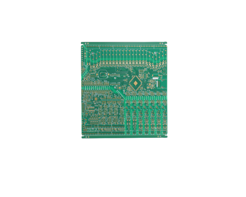
A printed circuit is a conductive pattern formed on an insulating substrate according to a predetermined design, consisting of printed circuits, printed components, or a combination of both. A printed circuit is a conductive pattern formed on an insulating substrate to provide electrical connections between components. It does not include printed components. The finished board of a printed circuit or printed circuit is called a printed circuit board or printed wiring board, also known as a printed board. Printed boards can be divided into two main categories: rigid printed boards and flexible printed boards, depending on whether the substrate used is rigid or flexible. This year also saw the emergence of rigid-flex printed boards. According to the number of layers of the conductor pattern, they can be divided into single-sided, double-sided, and multilayer printed boards. A printed board in which the entire outer surface of the conductor pattern and the surface of the substrate are on the same plane is called a flat printed board.
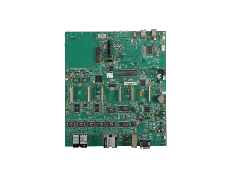
After electronic devices adopt printed circuit boards, due to the consistency of similar printed circuit boards, manual wiring errors can be avoided, and automatic insertion, automatic welding, and automatic detection of electronic components can be realized, ensuring the quality of electronic devices, improving labor productivity, reducing costs, and facilitating maintenance. Printed circuit boards have developed from single-layer to double-sided, multilayer, and flexible, each maintaining its own development trend. Due to the continuous development of printed circuit boards towards high precision, high density, and high reliability, the volume is continuously shrinking, and the cost is continuously decreasing, so printed circuit boards will still maintain strong vitality in the future development of electronic devices.
A Brief History of PCB Development
The basic concept of printed circuits was proposed in patents at the beginning of this century. In 1947, the US Aviation Administration and the US Bureau of Standards initiated a printed circuit technology seminar, which listed 26 different printed circuit manufacturing methods at that time. These are divided into six categories: coating method, spraying method, chemical deposition method, vacuum evaporation method, molding method, and powder compaction method. At that time, none of these methods could achieve large-scale industrial production.
Until the early 1950s, due to the solution of the adhesion problem between copper foil and laminate, the performance of copper-clad laminates became stable and reliable, and large-scale industrial production was realized. Copper foil etching became the mainstream of printed circuit board manufacturing technology. Development to this day. 20
In the 1960s, through-hole metallized double-sided and multilayer printed circuit boards achieved mass production. In the 1970s, due to the rapid development of large-scale integrated circuits and electronic calculators, the 1980s represented surface mount technology, and the 1990s represented multi-chip technology,
This has promoted the continuous progress of printed circuit board production technology, and a batch of new materials, new equipment, and new testing instruments have emerged one after another. Printed circuit production technology has further developed in the direction of high density, fine lines, multi-layers, high reliability, low cost, and continuous automated products.
The Role of Printed Circuits in Electronic Devices
(1) Provide mechanical support for the fixing and assembly of integrated circuits and other electronic components.
(2) Realize wiring and electrical connection or electrical insulation between integrated circuits and other electronic components.
(3) Provide the required electrical characteristics, such as characteristic impedance.
(4) Provide solder resist patterns for automatic soldering, and identifiers and graphics for component insertion, inspection, and maintenance.
How PCB Manufacturing Technology Will Change
1) Reduce lead content (2) Reduce formaldehyde usage (3) Progress of MID (4) Other materials
High-speed circuits
It is generally believed that if the frequency of a digital logic circuit reaches or exceeds 45MHZ~50MHZ, and the circuits operating at this frequency or higher already account for a certain proportion of the entire electronic system (for example, 1/3), it is called a high-speed circuit. In fact, the harmonic frequency of the signal edge is higher than the frequency of the signal itself. It is the rising and falling edges (or signal transitions) of the signal that lead to unpredictable results in signal transmission. Therefore, it is generally believed that if the line propagation delay is greater than 1/2 of the rise time of the digital signal driver end, then this Analog signals are high-speed signals and will produce transmission line effects. Signal transmission occurs at the moment when the signal state changes, such as the rise or fall time. The signal takes a fixed time to travel from the driver end to the receiver end. If the transmission time is less than 1/2 of the rise or fall time, the reflected signal at the receiver end will reach the driver end before the signal changes state. Conversely, the reflected signal will only reach the driver end after the signal changes state. If the reflected signal is strong, the superimposed waveform may change the logic state.
V-CUT
One method of forming a circuit board is to cut straight lines at the same positions on the top and bottom surfaces of the circuit board without cutting through, so that it can be manually broken or broken using a jig. A V-shaped groove is formed from the top and bottom of the circuit board, so it is called C-CUT.
Gold fingers
Refers to some circuit boards—such as network cards. The gold-plated wires on the panel are called gold fingers because of their finger-like shape.
RECOMMENDED NEWS

High-end Custom Services: SMT Chip Processing Meets Diverse Industry Needs


(Telephone contact)
Email:
Address: Room 502, Building 1, No. 13, Bohua 4th Road, Huangpu District, Guangzhou City
COPYRIGHT © 2025 Guangzhou Tongsen Electronic Technology Co., Ltd. All rights reserved.